Overview
The I2C Adapter is a USB to SPI bridge that uses off-the-shelf and inexpensive boards such as the
Raspberry Pi Pico, and control it using the python package i2c_adapter.
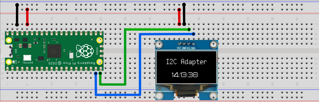
For example, the diagram below shows the wiring to control an I2C OLED display using
USB and Python API. The full code is provided in the examples directory of the github repository.
Examples
Writing and reading a I2C device 0x08 with the I2C Adapter at serial port COM7:
1from i2c_adapter import I2cAdapter
2
3i2c = I2cAdapter(port="COM7")
4i2c_addr = 0x08
5assert i2c.write(i2c_addr, bytearray([0]))
6data = i2c.read(i2c_addr,  20)
7print(data)
Scanning the I2C bus for devices:
1from i2c_adapter import I2cAdapter
2
3i2c = I2cAdapter(port="COM18")
4print(f"Scanning I2C bus 0x00 to 0x7f:")
5for adr in range(0, 127):
6    if i2c.write(adr, bytearray([0]), silent=True):
7        print(f"  - Found an I2C  device at 0x{adr:02x}")
Reading and writing auxiliary I/O pins:
 1import time
 2from spi_adapter import SpiAdapter, AuxPinMode
 3
 4# Customize for your system.
 5port = "COM18"
 6aux_out_pin = 0
 7aux_in_pin = 1
 8
 9# Configure the two aux pins.
10spi = SpiAdapter(port)
11spi.set_aux_pin_mode(aux_out_pin, AuxPinMode.OUTPUT)
12spi.set_aux_pin_mode(aux_in_pin, AuxPinMode.INPUT_PULLUP)
13
14# Access the two pins.
15i = 0
16while True:
17  i += 1
18  spi.write_aux_pin(aux_out_pin, i % 2)   # Generates a square wave
19  in_value = spi.read_aux_pin(aux_in_pin)
20  print(f"{i:03d}: Input pin value: {in_value}", flush=True)
21  time.sleep(0.5)
Supported Boards
The able below lists the currently supported boards. To make your own I2C Adapter, get one of these boards, and flash it according to the manufacturer’s instructions with the corresponding I2C Adpter firmware from https://github.com/zapta/i2c_adapter/tree/main/firmware/release.
- Example:
For the Raspberry Pico and similar RP2040 boards, flash it by connecting the board to your computer while holding the BOOTSEL button. Once your computer recognized the board as a new hard driver, release the button and copy the firmware file to that hard drive.
Board |
SDA, SCL |
Pullup ups |
Aux Pins |
|---|---|---|---|
GP 14, 15 |
Weak |
GP 0-7 |
|
Qwiic SDA |
2.2K |
GP 0-7 |
|
Qwiic SDA |
Weak |
GP 0-7 |
|
Qwiic SDA |
Weak |
GP 0-7 |
- Note:
The RP2040 contains weak I2C pullup resistors that are sufficient for many cases. If needed, add external 3K to 10K pullup resistors on the SDA and SCL lines.
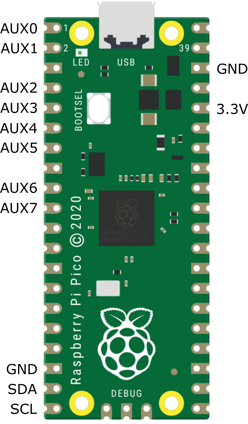
Raspberry PI Pico Pinout
The diagram below shows the pinout for the popular Raspberry Pi Pico. For the other supported board, consult the table above.
API Installation
The Python API package is available from PyPi at https://pypi.org/project/i2c-adapter and can be installed on your computer using pip:
pip install i2c_adapter
- Note:
The I2C Adapter boards appear on the computer as a standard CDC serial port and thus do not require driver installation.
API Reference
The i2c_adapter package provides the API to access I2C Adapter boards. To access an I2C Adapter,
create an object of the class I2CAdapter, and use the methods it provides.
- class i2c_adapter.AuxPinMode(value, names=None, *values, module=None, qualname=None, type=None, start=1, boundary=None)
Auxilary pin modes.
- class i2c_adapter.I2cAdapter(port: str)
Connects to the I2C Adapter at the specified serial port and asserts that the I2C responses as expcted.
- Parameters:
port (str) – The serial port of the I2C Adapter. I2C Adapters appear on the local computer as a standard serial port
- read(device_address: int, byte_count: int, silent=False) bytearray | None
Reads N bytes from an I2C device.
- Parameters:
device_address (int) – I2C device address in the range [0, 0xff].
byte_count (int) – The number of bytes to read. Should be in the range [0, 256].
silent (bool) – If true, supress printing of error messages. Useful when using the method to scan the I2C bus for devices. Default value is good for most other use cases
- Returns:
A bytearray with
byte_countbytes read, or None if an error- Return type:
bytearray
- write(device_address: int, data: bytearray | bytes, silent=False) bool
Write N bytes to an I2C device.
- Parameters:
device_address (int) – I2C device address in the range [0, 0xff].
data (bytearray or bytes.) – The bytes to write.
len(data)should be in the range [0, 256].silent (bool) – If true, supress printing of error messages. Useful when using the method to scan the I2C bus for devices. Default value is good for most other use cases.
- Returns:
True if ok, False if an error.
- Rtrype:
bool
- set_aux_pin_mode(pin: int, pin_mode: AuxPinMode) bool
Sets the mode of an auxilary pin.
- Parameters:
pin (int) – The aux pin index, should be in [0, 7].
pin_mode (AuxPinMode) – The new pin mode.
- Returns:
True if OK, False otherwise.
- Return type:
bool
- read_aux_pins() int | None
Reads the auxilary pins.
- Returns:
The pins value as a 8 bit in value or None if an error.
- Return type:
int | None
- write_aux_pins(values, mask=255) bool
Writes the aux pins.
- Parameters:
values (int) – An 8 bits integer with the bit values to write. In the range [0, 255].
mask (int) – An 8 bits int with mask that indicates which auxilary pins should be written. If the corresponding bits is 1 than the pin is updated otherwise it’s left as is.
- Returns:
True if OK, False otherwise.
- Return type:
bool
- read_aux_pin(aux_pin_index: int) bool | None
Read a single aux pin.
- Parameters:
aux_pin_index (int) – An aux pin index in the range [0, 7]
- Returns:
The boolean value of the pin or None if error.
- Return type:
bool | None
- write_aux_pin(aux_pin_index: int, value: bool | int) bool
Writes a single aux pin.
- Parameters:
aux_pin_index (int) – An aux pin index in the range [0, 7]
value (bool | int) – The value to write.
- Returns:
True if OK, False otherwise.
- Return type:
bool
- test_connection_to_adapter(max_tries: int = 3) bool
Tests connection to the I2C Adapter.
The method tests if the I2C adapter exists and is responding. It is provided for diagnostic purposes and is not needed in typical applications.
- Parameters:
max_tries (int) – Max number of attempts. The default should be good for most case.
- Returns:
True if connection is OK, false otherwise.
- Return type:
bool
The Wire Protocol
The i2c_adapter package communicates with the SPI Adapter board by sending commands
and receiving command responses on a serial connection. The commands and responses are made of a plain sequence of
‘binary’ bytes with no special encoding such as end of line or byte stuffing. For
an updated specification of the commands and their wire representation see the
firmware protocol implementation.
Firmware Development
The firmware is written in C++ and is developed as a platformio project under Visual Studio Code. The following sections summarize the key aspect of the firmware development.
Project Structure
The platformio project resides in the firmware/platformio directory of the I2C Adapter repository https://github.com/zapta/i2c_adapter, the project configuration is in the platformio.ini file and the source code is in the src directory.
Setting up the environment
Install Microsoft’s Visual Studio Code (‘VSC’)
In VSC, add the extension ‘platformio’
Clone the I2C Adapter github repository on your computer.
Use VSC’s ‘file | open-folder’, to open the ‘platformio’ directory in your local repository.
After platformio will complete installing the necessary tools, click on the ‘build’ icon in the status bar to verify that the project builds correctly.
Testing a new firmware version
Make the changes in the source code.
Connect a compatible board to your computer.
Select in the status bar the board target that matches your board.
Use the ‘upload’ button in the status bar to build and upload the binary to the board.
Generating new binaries
Run the python script ‘build_env.py’ and it will build binaries for all the targets and will copy them to release directory.
Adding a new board
Board definitions resides in platformio.ini and in src/board.cpp and the amount of refactoring needed to add a board depends how close it is to the existing boards. Adding a typical board includes adding:
A new target to platformio.ini
A new section in src/boards.cpp.
A new row to the documentation’s list.
A new binary to the release.
Contact
Bug reports and contributions are welcome. You can contact the team and fellow users at the gibhub repository at https://github.com/zapta/i2c_adapter.